Speckle patterns & anamorphosis
| Summary | |
|---|---|
| Date | Summer 2021 - Winter 2022 |
| Tags | digital image correlation, speckle pattern, anamorphosis, python |
| Partners | Yvan Dilem, Stéphane Hu |
Digital Image Correlation (DIC) is a 2D or 3D (stereo-DIC) optical method that allows for the measurement of the displacement field between two camera images. These images contain a speckle pattern that is disposed (painted, deposited, etched,…) on the surface of the specimen that will be studied. It is usually made of black dots disposed over a white surface, it is a critical for any experiment involving DIC. Since DIC uses subsets of the speckle pattern in order to derive a displacement measurement, the quality of the speckle pattern must be optimized as to minimize the noise and maximize the accuracy of the measurement performed. Examples of speckle patterns are presented in the figure below. There are methods that were designed to automatically generate an optimized speckle pattern..
Left: A honeycomb 3D printed specimen covered with a speckle pattern. Right: Interfacial debonding of a 1mm in diameter PTFE fiber embedded in Epoxy, tensile load is applied along the vertical direction [^7]
For the highest possible accuracy, we ideally want subsets as small as possible. However, we also want subsets to be unique enough so that they cannot be mistaken with another subset: the pattern made by the black dots is like the fingerprint of a subset. So we try to make the subset size as small as possible while having enough uniqueness in each subset, and as mentioned above, tools and methods are available to optimize such a speckle pattern. The figure below shows a speckle pattern as seen during the deformation of a part, and as it is seen by the camera sensor.
 The left side of the figure presents a flat surface undergoing shear (shown by the yellow arrows). The flat surface is covered with a speckle pattern. A black grid showing an arbitrary subset size is drawn over the speckle pattern. The right side of the figure shows a single subset as seen by the sensor of the camera. The red lines present the initial and final shape of the subset 1.
However, in the case where the point of view of the camera is not orthogonal with the surface being studied, or the surface being studied is not completely flat, speckle pattern optimizations since the point of view of the camera skews and distorts the observed speckle. This drastically reduces the quality of the measurement and its accuracy. We have thus devised a novel approach that relies on the mathematics of the anamorphosis method in order to adress this issue. You have probably encountered anamorphosis through an art installation for which you had to look from a specific point of view in order to be able to see the actual work of art. If not, then you surely have noticed that large messages written on the road for the driversM benefit (speed limitations, closed roads) appear to be distorted when seen from the edge of the road while they appear perfectly fine from a car on the road. The mathematics of the anamorphosis method is what makes this possible. The following figures present two examples of anamorphosis.
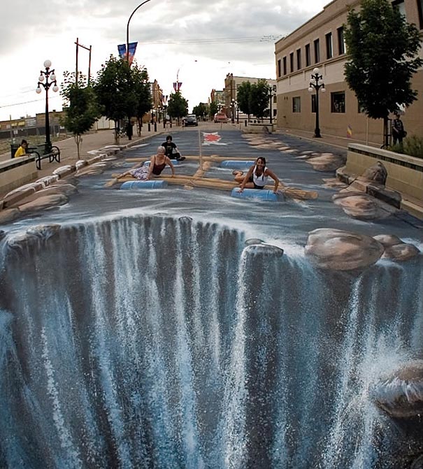
Left: A drawing of a surreal landscape that becomes a figure when projected on a cylidrical miror (source unkown). Right: Confusing waterfalls drawn with chalk on the ground. The viewer must look from the point of of the current photo to see the desired perspective effect 2
In some cases, it is impossible to set up a camera to observe a flat surface from an orthogonal point of view. The photography below shows the point of view of a camera from the passenger window of an aircraft as an example of such a case. Preliminary experiments are showing that the usage of anamorphosis strongly improves the accuracy of measurements obtained with DIC and can thus be used to improve the accuracy of measurements in such cases.
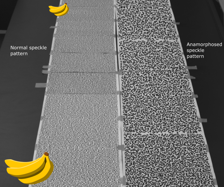
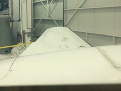
Left: The point of view of a camera from the passenger window of a small aircraft. Let’s suppose that we want to apply DIC on the aircraft wing while it’s flying. We would have to observe a speckle pattern from that point of view, which is not ideal. Right: The photography shows a normal speckle pattern. The speckle pattern on the right was anamorphosed with respect to the position of the current camera. The average dot size of both speckles is the same. Bananas were added to help the viewer grasp the spatial disposition of the cameras with respect to the speckles.
-
From r/confusing_perspective ↩
Leave a comment